


How to Install a Reverse Osmosis Filter System
Install a Reverse Osmosis Water Filter DIY
If you're looking to install an under-counter Reverse Osmosis (RO) drinking water filtration system yourself, we guide you through each step of the process to avoid any unexpected challenges. Opting for a DIY installation of a reverse osmosis system can lead to significant savings.
Keep in mind that there are many different types of reverse osmosis systems on the market, and the guidelines below may not apply to your specific system. Contact the manufacturer of your system for product specific installation instructions.
Before getting started, make sure you have these items ready:
Tools Needed for RO Install
- Wrenches Sizes 7/16”, 9/16”, ½” & 5/8”
- Phillips ScrewDriver- Drill With 3/8”
- Chuck Drill Bits Sizes ¼” or 1 1/8” For Air Gap faucet
Reverse Osmosis Install Instructions DIY
The following installation details are given as general information only. Please consult the owner’s manual and manufacturer's installation instructions for your specific make and model.
Read and become familiar with all instructions and parts before beginning the Reverse Osmosis installation process.
1. Installation Location
Before you get started, clean out under the sink and make sure there is ample space to install the RO system. Locate the “cold” water shut off valve and sink drainpipe.
2. Close the Cold-Water Valve
Shut off the “cold” water supply under the sink or the location where the system will be installed. If the existing “cold” water valve is inoperable, the water supply to the house must be shut off. Once the water is shut off, relieve the line pressure by turning on the cold-water faucet.
3. Connect to Cold Water Line
There are several options when connecting the reverse osmosis unit to the cold-water source. They are:
RO replacement filters should be installed based on the following schedule:
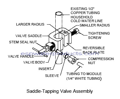
A. Saddle valve (Standard) – Assemble saddle valve clamp on the “cold” water line. Turn the pipe clamp adjustment plate to fit the contour of the pipe. (Small radius for 3/8” pipe, larger radius for 7/16” through 5/8” pipe). Tighten bolt so saddle valve is firmly attached to feed water pipe (be careful not to over tighten).
B. Ez adapter. (Optional): Use some Teflon tape to prevent leaks. Assemble 90-degree needle valve into the feed adapter.
For "Flex line" installation: Disconnect the flex line at the sink and install the feed adapter. Reconnect the flex line to the adapter.
For "Solid line" installation: Disconnect the line at the sink cut off approximately ¾” off the line. Install the feed adapter and reconnect line to the feed adapter.
4. Drain Line Connection
NOTE: If the drain line pipe is corroded, we strongly suggest replacing it.
At a point approximately six inches above the trap, drill a 5/16” diameter hole through one wall of the pipe. Next, attach the drain clamp; making sure that the hole in the clamp is aligned with the hole in the pipe. Use a punch or drill bit to align the holes while tightening the clamp. Be careful not to over tighten the clamp.
5. Prepping the RO Faucet
The faucet must be positioned with aesthetics, function and convenience in mind. An ample flat area is required for the faucet base, so the base nut can be properly tightened.
Conditions may exist which eliminate the need to drill a hole in the sink, such as:
- If a hole previously installed in the sink, covered by a chrome plate cover, then simply remove the cover, and mount the faucet.
- If a spray hose that may not be functioning or needed. Remove the spray hose and plug the outlet under the main faucet. If the sprayer uses a diverter at the base of the spout remove it, as the sprayer diverter may pop up and shut the water off to the main faucet.
- If space is not available on the upper sink area, the faucet can be in the countertop close to the edge of the sink. Be careful to watch for obstructions below the counter such as drawers, cabinet walls, support braces etc. If the countertop is ceramic tile the method for drilling the faucet hole is the same as for drilling a porcelain sink.
- The drilling process although not complicated, requires a certain amount of caution and preparation. Porcelain enameled sinks can be chipped if care is not exercised when drilling the hole for the faucet assembly.
There are several ways of drilling the holes in to porcelain sinks without chipping; we have found these two methods work very well.
1 Using a carbide grinding wheel, grind away the porcelain where the ¼” diameter hole is to be drilled. Drill a ¼” diameter hole through the metal. This method results in a very clean and smooth hole.
2 Using a heavy-duty variable speed drill and a carbide tip drill bit, carefully drill a ¼” diameter hole through the porcelain and metal sink.
For stainless steel sinks, drill a ¼” diameter hole. Lightly file the edge of the hole to make sure it is smooth and free of any burrs. Caution: Do not allow metal chips to remain on the porcelain surface of the sink for any length of time, the metal chips will stain the sink and be very difficult to remove.
6. Installing the Faucet
Once the hole has been drilled in the sink, the faucet stem may be inserted in the hole. Be sure the faucet body, faucet base and the rubber faucet base washer are in place above the sink.
Install the star lock washer and nut on the faucet stem under the sink and tighten firmly while aligning faucet in the desired direction. Once the faucet is installed, attach the ¼” tubing onto the bottom of the faucet stem and tighten.
Note: Some states require the use of an air gap faucet. To assure compliance, check your local plumbing code. Locate the drain connection away from the garbage disposal to prevent potential contamination and system fouling.
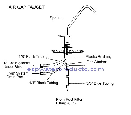
Air gap faucet installation instructions:
Place the chrome washer and rubber washer on the base of the faucet. Slip the ¼” black line from the system through the hole in the sink. From the topside of the sink, slip the ¼” black line from system onto the barbed fitting located in the faucet base. The 3/8” black line from barb output is to be run as straight downhill as possible to the drain clamp. Avoid low spots or loops. Place faucet into the hole of the sink then from underneath sink, replace parts and tighten the hold down nut. Connect the ¼” blue line to the threaded faucet stem.
7. Unit Location
Place the system and the water storage tank in an area under the sink so they are out of the way. If the system is to be hung on the wall of the cabinet, be sure to leave at least 3 inches from bottom of RO housings to cabinet floor. Drill two 1/8” pilot holes that match up to the mounting holes in the systems bracket, mount the system to the cabinet wall.
8. System Hook up
Remove any red caps from the end of the tubing. There may be water present in these lines if the system was wet tested at the factory, so keep a towel handy to wipe up any water.
Note: color of lines may vary from manufacturer to manufacturer – we have attempted to use industry standard colors in describing the system hook up procedures.
8A. Connect the units orange feed water line to the saddle valve or EZ adapter installed on the cold-water line. Use the plastic delrin sleeve that is provided in the installation kit and discard any brass ferrules that may have been provided.
8B. Connect the black line from the unit directly to the drain clamp assembly. If an air gap faucet is used see instruction listed under air gap faucet installation instructions.
8C. Connect the green line to the RO water storage tank.
8D. Connect the blue line from the unit to the faucet.
Note: Make sure all inserts, sleeves and ferrules provided in the installation kit are used.
THIS IS A GOOD TIME TO DOUBLE CHECK AND MAKE SURE ALL YOUR FITTINGS ARE TIGHT AND THE TUBING IS SECURE IN THE FITTINGS.
9. Starting Up the RO System
9A. Turn off the storage tank ball valve, this will ensure no water can enter the tank. Slowly turn on the cold-water supply valve to the sink. If you have not already done so, open the valve of the cold-water self-piercing valve (turn counterclockwise to open). Check for any leaks around the valve. If any leaks are detected turn off cold water supply valve and make necessary repairs.
9B. Open the reverse osmosis faucet on the sink. You will hear a gurgling noise. This is normal air being cleared from the system. It will take approximately 10-15 minutes before you actually see water dripping from the reverse osmosis faucet. (Flip the faucet handle up to keep the faucet open during this time.) The initial water dripping from the faucet may be black in color; this is the water flushing carbon fines from the carbon post filters. Allow the water to drip from the faucet for 10-15 minutes then close the faucet
9C. Now open the ball valve on the reverse osmosis storage tank, which will allow the tank to fill. This will take approximately 4-10 hours. During this period of time check all fittings for any leaks. If any leaks are found turn off cold-water line and make the necessary correction. Once the tank is full open the faucet and drain the system completely (until you are getting only a drip from the faucet). Shut the reverse osmosis faucet off and allow the system to re-fill.
9D. It is recommended on new installations that you drain the system 3 times prior to use.
9E. Make a daily check for any leaks during the first week after installation and check for leaks occasionally thereafter.
You might also refer to our RO Troubleshooting Guide to answer common RO issues including slow water flow, noisy drain or faucet, and more. Our suggestions on what to know before purchasing a reverse osmosis system might also prove helpful.
Expert Tip
Most reverse osmosis drinking water systems utilize John Guest fittings, which are popular quick-connect fittings that make installation easy without the need for tools. Also, their push-fit design ensures secure tubing connections, minimizing the risk of leaks. Learn how to connect and disconnect your RO system tubing with John Guest fittings.
Top-Selling Reverse Osmosis Drinking Water Systems
When to Call a Professional
Know your limitations. If you're worried you don't have the right tools, background knowledge, or time to install the reverse osmosis system, we recommend hiring a local plumber. You can save a lot of money by purchasing the Reverse Osmosis System online, and then hiring a plumber to do the install. Many of our customers go this route.
Recommendations When Hiring a Local Plumber to Install RO System
Plumber Reviews Matter
If you don't already have a plumber whom you know and trust, check out local plumber reviews on the internet. Popular review sites include:
-
- Yelp
- Angie's List
- Better Business Bureau
- Google Reviews can be found by signing into Google and opening Google Maps. Search for "plumber" to see reviews and star ratings for plumbers near you.
Call Around Before Hiring
Once you've identified a few reputable plumbers in your area, make phone calls and ask questions.
-
- Tell them you have already purchased an RO system and are simply looking to have it installed.
- Ask if they're familiar with RO installations.
- Ask if you can pay them their hourly rate to install a system.
- Ask how much time a typical RO installation takes.
- Ask for references.
RO Water Production Capacity Rates
The inlet water pressure, water temperature, and the amount of TDS (total dissolved solids) in your water can affect the water filtration production capacity of your new RO drinking water system.
Operating on typical home water pressure, a reverse omosis system will filter, store and dispense water with water pressure between 40 – 65 psi.
For the charts below, the CTA (Cellulose Triacetate) and TFC (composite) Membranes are based on 10 gallons per day reverse osmosis membranes.
- 40 PSI
- 50 PSI
- 60 PSI
- 70 PSI
- 80 PSI
| 40 F | 50 F | 60 F | 70 F | 80 F | 90 F | |
| 100 TDS ppm | 3.0 GPD | 3.6 GPD | 4.4 GPD | 5.4 GPD | 6.6 GPD | 8.0 GPD |
| 500 TDS ppm | 2.4 GPD | 2.8 GPD | 3.4 GPD | 4.2 GPD | 5.0 GPD | 6.3 GPD |
| 1000 TDS ppm | 1.5 GPD | 1.8 GPD | 2.2 GPD | 2.7 GPD | 3.4 GPD | 4.0 GPD |
| 40 F | 50 F | 60 F | 70 F | 80 F | 90 F | |
| 100 TDS ppm | 4.0 GPD | 4.8 GPD | 5.9 GPD | 7.3 GPD | 8.8 GPD | 10.6 GPD |
| 500 TDS ppm | 3.2 GPD | 4.0 GPD | 4.9 GPD | 6.0 GPD | 7.3 GPD | 9.0GPD |
| 1000 TDS ppm | 2.4 GPD | 2.9 GPD | 3.6 GPD | 4.3 GPD | 5.4 GPD | 6.7 GPD |
| 40 F | 50 F | 60 F | 70 F | 80 F | 90 F | |
| 100 TDS ppm | 5.0 GPD | 6.2 GPD | 7.6 GPD | 9.3 GPD | 11.4 GPD | 13.8 GPD |
| 500 TDS ppm | 4.4 GPD | 5.4 GPD | 6.6 GPD | 8.0 GPD | 9.7 GPD | 12 GPD |
| 1000 TDS ppm | 3.6 GPD | 4.4 GPD | 5.4 GPD | 6.6 GPD | 8.0 GPD | 9.8 GPD |
| 40 F | 50 F | 60 F | 70 F | 80 F | 90 F | |
| 100 TDS ppm | 6.3 GPD | 7.6 GPD | 9.3 GPD | 11.4 GPD | 13.9 GPD | 17 GPD |
| 500 TDS ppm | 5.6 GPD | 6.8 GPD | 8.3 GPD | 10.2 GPD | 12.5 GPD | 15.3 GPD |
| 1000 TDS ppm | 4.8 GPD | 5.8 GPD | 7.0 GPD | 8.7 GPD | 10.5 GPD | 13 GPD |
| 40 F | 50 F | 60 F | 70 F | 80 F | 90 F | |
| 100 TDS ppm | 7.1 GPD | 8.8 GPD | 10.6 GPD | 13 GPD | 16 GPD | 19.6 GPD |
| 500 TDS ppm | 6.6 GPD | 8.0 GPD | 9.8 GPD | 12.1 GPD | 14.7 GPD | 17.9 GPD |
| 1000 TDS ppm | 5.8 GPD | 7.0 GPD | 8.7 GPD | 10.5 GPD | 12.8 GPD | 15.6 GPD |
Notes:
- Product water recovery: 25-30%
- Approximate dissolved solids rejection rate: 85-99%
- Total Dissolved Solids (TDS) are measured in parts per million (ppm)
- Production rate listed above required a holding tank at 7-10 psi. Due to the many variables involved with different water supplies, the above tables are provided only for the purpose of making estimates.
- Individual membranes may vary as much as +/- 15%
- If your RO system seems to be producing less filtered water than expected, check out our page that explains how to determine the current production rate of your RO unit.
Still Have Questions about Installing a Reverse Osmosis System?
If you have additional questions, our team of water experts are always happy to take your calls Monday through Friday, 8 am to 5 pm. That's one of the perks of purchasing from us! When you call in, we will first pull up your order and verify the system is purchased from ESP Water Products. That way, we will know exactly what system you're working with and can best help you. For example, do you know if you want an "air gap" or "non-air-gap" faucet?
Unfortunately, due to time constraints we cannot provide installation or troubleshooting help for systems not purchased through our website. We recommend you call the company or store where you purchased your system.
Answers To Your Most Common Questions
Is Your Reverse Osmosis Water Flow Slow?
Is the water coming out of your RO faucet slower than you think it should be? Here are six reasons for slow water flow from your reverse osmosis drinking water system.
Read More>
Best Emergency Water Systems for Households and Small Groups
In recent years, we’ve witnessed the devastation and destruction left by earthquakes, fires, flooding, and hurricanes. Discover how you can ensure an ample supply of potable water is available in times of emergencies and disasters.
Read More>
Do I Need a Whole House Reverse Osmosis System?
If you like the water produced by your reverse osmosis drinking water system at your kitchen tap, wouldn’t it make sense to have RO water throughout the home? The answer may surprise you.
Read More>